- 您现在的位置:买卖IC网 > Sheet目录1994 > DS3232SN#T&R (Maxim Integrated Products)IC RTC W/TCXO 20-SOIC
Extremely Accurate I2C RTC with
Integrated Crystal and SRAM
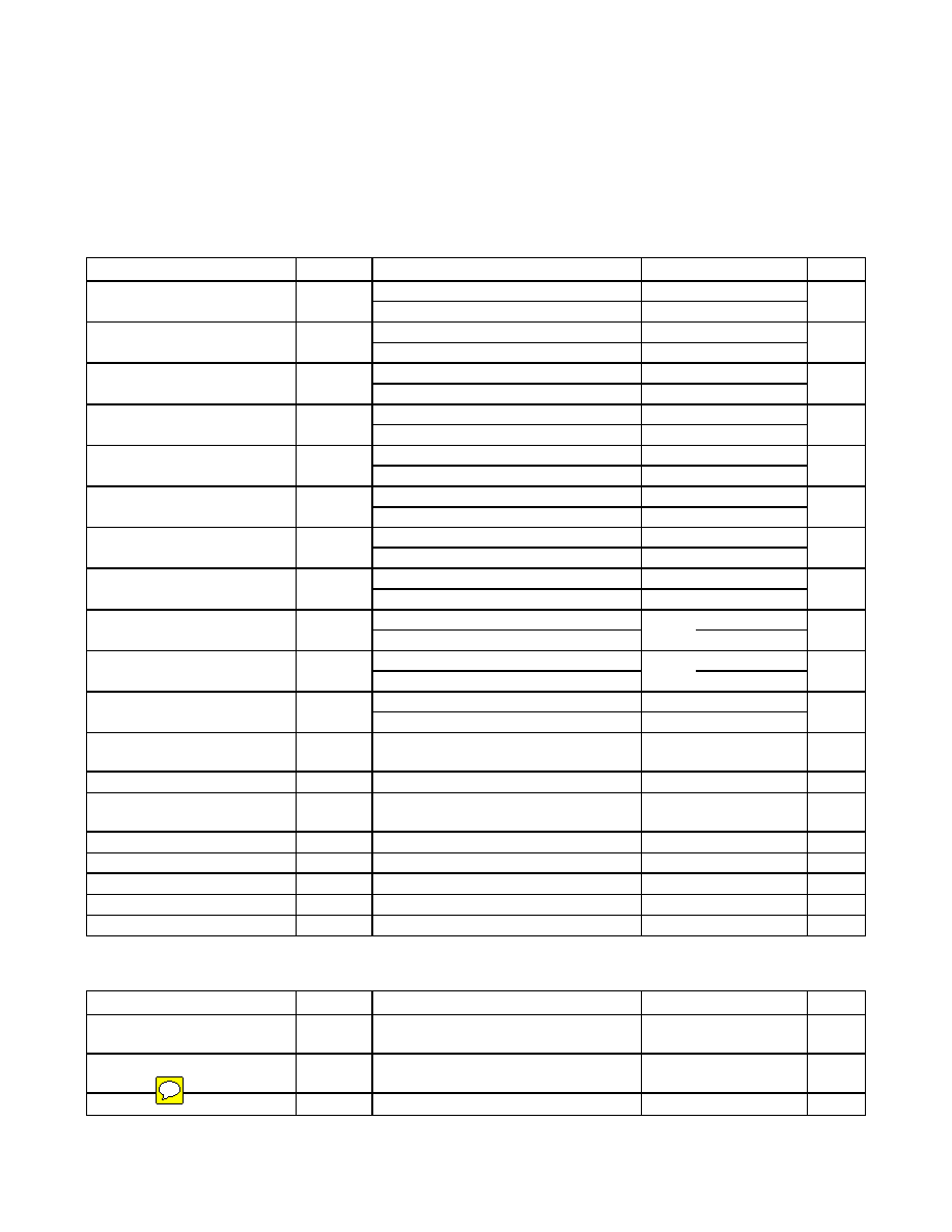
AC ELECTRICAL CHARACTERISTICS
(Active supply (see Table 1) = 2.3V to 5.5V, TA = -40°C to +85°C, unless otherwise noted.) (Note 2)
PARAMETER
SYMBOL
CONDITIONS
MIN
TYP
MAX
UNITS
Fast mode
100
400
SCL Clock Frequency
fSCL
Standard mode
0.04
100
kHz
Fast mode
1.3
Bus Free Time Between STOP
and START Conditions
tBUF
Standard mode
4.7
s
Fast mode
0.6
Hold Time (Repeated) START
Condition (Note 7)
tHD:STA
Standard mode
4.0
s
Fast mode
1.3
25,000
Low Period of SCL Clock
tLOW
Standard mode
4.7
25,000
s
Fast mode
0.6
High Period of SCL Clock
tHIGH
Standard mode
4.0
s
Fast mode
0
0.9
Data Hold Time (Notes 8, 9)
tHD:DAT
Standard mode
0
0.9
s
Fast mode
100
Data Setup Time (Note 10)
tSU:DAT
Standard mode
250
ns
Fast mode
0.6
Start Setup Time
tSU:STA
Standard mode
4.7
s
Fast mode
300
Rise Time of Both SDA and SCL
Signals (Note 11)
tR
Standard mode
20 +
0.1CB
1000
ns
Fast mode
300
Fall Time of Both SDA and SCL
Signals (Note 11)
tF
Standard mode
20 +
0.1CB
300
ns
Fast mode
0.6
Setup Time for STOP Condition
tSU:STO
Standard mode
4.7
s
Capacitive Load for Each Bus
Line (Note 11)
CB
400
pF
Capacitance for SDA, SCL
CI/O
10
pF
Pulse Width of Spikes That Must
Be Suppressed by the Input Filter
tSP
30
ns
Pushbutton Debounce
PBDB
250
ms
Interface Timeout
tIF
(Note 12)
25
35
ms
Reset Active Time
tRST
250
ms
Oscillator Stop Flag (OSF) Delay
tOSF
(Note 13)
100
ms
Temperature Conversion Time
tCONV
125
200
ms
POWER-SWITCH CHARACTERISTICS
(TA = -40°C to +85°C)
PARAMETER
SYMBOL
CONDITIONS
MIN
TYP
MAX
UNITS
VCC Fall Time; VPF(MAX) to
VPF(MIN)
tVCCF
300
s
VCC Rise Time; VPF(MIN) to
VPF(MAX)
tVCCR
0s
Recovery at Power-Up
tREC
(Note 14)
125
300
ms
DS3232
4
Maxim Integrated
发布紧急采购,3分钟左右您将得到回复。
相关PDF资料
DS3234S#
IC RTC W/TCXO 20-SOIC
DS32C35-33#T&R
IC RTC ACCURATE I2C 3.3V 20-SOIC
DS3911T+
IC DAC 10BIT I2C QUAD 14TDFN
DS4000KI/WBGA
IC OSC TCXO 19.44MHZ 24-BGA
DS4026S+WCN
IC OSC TCXO 25MHZ 16-SOIC
DS4100HW+
IC OSC CLOCK 100MHZ 10LCCC
DS4266P+
IC OSC CLOCK 266MHZ 10-LCCC
DS4302Z-020/T&R
IC DAC 5-BIT SGL 0-2.0V 8-SOIC
相关代理商/技术参数
DS3232SN#-W
功能描述:实时时钟 RoHS:否 制造商:Microchip Technology 功能:Clock, Calendar. Alarm RTC 总线接口:I2C 日期格式:DW:DM:M:Y 时间格式:HH:MM:SS RTC 存储容量:64 B 电源电压-最大:5.5 V 电源电压-最小:1.8 V 最大工作温度:+ 85 C 最小工作温度: 安装风格:Through Hole 封装 / 箱体:PDIP-8 封装:Tube
DS3234
制造商:MAXIM 制造商全称:Maxim Integrated Products 功能描述:Extremely Accurate SPI Bus RTC with Integrated Crystal and SRAM
DS3234_07
制造商:MAXIM 制造商全称:Maxim Integrated Products 功能描述:Extremely Accurate SPI Bus RTC with Integrated Crystal and SRAM
DS3234_08
制造商:MAXIM 制造商全称:Maxim Integrated Products 功能描述:Extremely Accurate SPI Bus RTC with Integrated Crystal and SRAM
DS3234_10
制造商:MAXIM 制造商全称:Maxim Integrated Products 功能描述:Extremely Accurate SPI Bus RTC with Integrated Crystal and SRAM
DS3234_BREAKOUT_
制造商:MCM 功能描述:DS3234 BREAKOUT BOARD 制造商:PREMIER FARNELL 功能描述:DS3234 BREAKOUT BOARD
DS3234_BREAKOUT_B34
制造商:Distributed By MCM 功能描述:DS3234 Real Time Clock Breakout Board
DS3234S
制造商:MAXIM 制造商全称:Maxim Integrated Products 功能描述:Extremely Accurate SPI Bus RTC with Integrated Crystal and SRAM